en English
Untitled English subtitles
Report a problem
Advertisement
English transcript
So students we meet again for the third lecture on shear strength of soil. We had 2 lectures
where we have covered quite a bit of ground on certain very important concepts relating
to shear strength of soil. Notably we spent a lot of time in understanding an elegant
graphical procedure called the Mohrís circle procedure for determining the stresses at
a point on any arbitrary plane. You may recall, the reason why we did was we need to know
what is the stress acting on any given plane and to test according to some strength criterion
or failure criterion whether or not shear failure will take place along that plane.
And thatís what shear strength of soils is all about. Given a set of stresses will the
soil fail and if so along which plane and thatís what we will be able to determine.
Once we know the so called shear strength parameters or the strength parameters of a
soil against shear. Today we will go further a head from what we saw in the last lecture.
We shall go ahead and see some typical strength tests which are being usually done in order
to get the strength parameters the so called cohesion and friction of the soil. There are
many methods; we had in fact briefly gone through all methods as an overview in the
first lecture. In todayís lecture we shall be covering some of these tests in some detail.
We may have to devote one more lecture to understand these tests a little more in detail.
The first test that we shall be seeing at some length is the direct shear test DST.
The second is the triaxial shear test TST, the third one is the unconfined compression
test which is sometimes called as unconfined compressive strength test UCS or sometime
it is called as the UCC unconfined compression test. The last one is the vane shear test.
We shall be essentially seeing the first 2 which I have marked here with this symbol.
We shall see the first 2 test in detail today. We may have to devote some more time to study
them a little more in detail later and then the last two we shall take up later. Whatever
we see today I will illustrate with a couple of example as well
Now there are many ways in which this topic of shear strength can be presented. After
all what we need is what is the shear strength of a soil? Now the shear strength of a soil
depends on many factors. So depending upon the factor that you are using a yard stick,
you can study this chapter of shear strength of soils in different perspective. If you
are looking at the type of test thatís being conducted, the equipment thatís being used
then we have the classification which I showed in the previous slide. That is the direct
shear test, the triaxial shear test, the vane shear test and so on. The yard stick that
has been used is the way in which the shear stress is being conducted. In the direct shear
test as we will be seeing, there is a predefined plane along which the soil is sheared.
In the triaxial shear test on the other hand we try to simulate the natural actual site
stress state and then allow the soil to fail along the weakest plane. In the unconfined
compressive strength test which is a very special case of the triaxial shear test, once
again we allow the soil to fail along the weakest plane. In the vane shear test, we
create a failure plane by rotating a vane inside the soil and try to study what is the
resistance that has been mobilized along that known plane or surface. Another yard stick
that we shall be seeing perhaps not today is the type of test conditions that we provide
during testing. Notably the condition with respect to movement
of water, you know how important water is. Whenever we shear a soil which is say saturated
or which has water in it, the water will try to move out. Now if you donít provide the
facility for the water to move out or if the soil is not pervious enough to allow the water
to move out at a reasonable rate then we have what is known as the undrained condition.
Under all other circumstances when water is able to move out freely, flow free out of
the sample which is being tested, we have the drained condition. So depending upon the
type of condition that you use whether it is drained or undrained, the soil will mobilize
and exhibits and manifest different strengths. And therefore the type of test is important
and we can use that as a yard stick for dividing the different types of tests and understanding
them.
There is also another yard stick that is the nature of the soil itself. Is the soil cohesive
or cohensionless? Depending upon the type of soil its response will vary according to
the type of test we conduct. And therefore we need to also study the type of soil and
its effect on the shear strength. So these are the 3 possible yard stick. Letís see
what is the importance of type of equipment that is used and whatís the type of test
that we conduct. So we shall be now seeing the direct shear stress. First test that we
shall see in detail is the direct shear test. Now here is a diagram showing a schematic
of the direct shear apparatus. See here, this is a metallic container what you see here
is a metallic container.
This upper portion is a part of the same container, the container is split into two halves and
there is what is known as the yolk to which a proving ring can be attached, is fixed.
And the soil specimen is kept in this container and the specimen again is kept in such a way
that there is a small gap between the 2 parts of this container. So that the upper portion
can be moved relative to the lower portion. Then on this side you have dial gauges to
measure the movement of the upper part and on the top of the specimen we have here a
loading plate on which is the normal load applied. So effectively what we have tried
to do here is, you have taken a sample of soil, we are trying to apply the kind of load
that it is experiencing in the field and then we are applying a shear force a tangential
force and make it fail and then see how it fails and what is the resistance it has mobilized
at the time of failure.
So the component of this so called shear box are, there is this container. Then there is
this cap which is the loading plate. There is a dial gauge to measure the displacement;
there are rollers to permit the bottom portion also to move if required, there is a porous
stone at the bottom of the specimen and at the top. And there is a dial gauge at top
again to measure the volume change that will occur when the specimen is sheared and the
upper portion tends to move outward and upward. These porous stones permit drainage of water.
Now as I said drainage is very important depending upon the condition of drainage whether we
allow drainage or not or whether the drainage allowed is slow or fast depending on these
conditions we will have the so called drained or undrained state and the behavior of the
soil will vary and we shall be seeing shortly how this drained conditions really exists
in a direct shear test do they or not. Here is where we apply the shearing force; this
green arrow shows the shearing force. So in effect this describes what a shear stress
direct shear tests is all about.
The specimen is typically 6 centimeter by 6 centimeters in plan area and 10 millimeters
in each half, so a total of 20 millimeters. A normal load is applied first that simulates
the confinement that the soil is experiencing in the field. After you apply the normal load
and after you assure that the confinement and its effect have been recreated. Then we
apply the tangential force until failures occurs. And the tangential force at failure
divided by the area of cross section is the shear stress that the soil is subjected to.
And now at the time of failure if you plot the shear stress and the normal stress for
atleast 3 different tests with soils specimen molded at different moisture contents or different
densities and we plot a graph which we shall be seeing later. We can evaluate and get the
2 shear stress strength parameters, cohesion and angle of internal friction.
Letís proceed. Here are 2 views of direct shear test; here is one direct shear test
very old and very conventional. Here is a slightly improved and better version, the
different is in the application of the normal load and shear force here. The second one,
the diagram on the right hand side is a motorized device to apply the shear force. The components
of these boxes are one specimen so this is where the specimen is kept; this is how the
container looks. The normal load is applied here through this lever arrangement here also
you can see this lever arrangement for applying the normal load. Then comes the motorized
shear load application here you see the motor here and here the motor is not very visible
but there is a motorized arrangement here as well.
In earlier versions of this the application of the shear load was also manual and then
we have the proving ring to measure the tangential load and then the dial gauge here to measure
the vertical displacement. So this is how a direct shear apparatus looks. There are
two types of test devices. We have to apply a shear force to the soil, we have to allow
the drainage to take place if we want to do a drain test. All this implies that there
has got to be a certain rate of shear which should be sufficiently slow considering the
type of soil we have to permit water flow. Obviously the rate of shear will vary depending
upon the type of soil, its porosity or its coefficient of permeability and the flow of
water. Therefore we need to have the facility to have different shear strain rates.
Itís possible to also control the application of the shear force not only by controlling
the shear strain rate but also by applying the load itself in increments in such a way
that the shear stress applied is in certain increment. So we can either control the strain
at which the movement takes place or we can control the stress thatís applied. Accordingly
we will have a strain controlled device where shear deformation is applied at a constant
strain rate till failure and even beyond if we are looking for testing beyond the failure
state as well. And it gives good loading control because it is very easy to have a mechanical
device, reluctive mechanical device a motor to be precise by which constant strain or
a constant rate of movement of the shear box can be very easily achieved.
On the other hand we also have this stress controlled equipment where the shear load is applied at uniform
increments until deformation ceases. Here itís difficult to identify the point of failure
as we have done in this strain controlled equipment and therefore we keep loading in
uniform adequate intervals until we find that for any given load the deformation come to
a halt and then we apply the next increment. This goes on until the sample finally fails.
Now let us look at the same 2 equipment once again. Both of these are conventional equipment,
both are strain controlled because here there is a motor, here there is a motor which makes
the upper portion of the container here to move at a uniform rate of displacement, same
thing here.
On the other hand here is an equipment which is very sophisticated and microprocessor control
which is also a strain control device but it is digital, it gives you all digital display,
it gives you 100% control over application of loads both normal and tangential. So this
is the latest modern version of the direct shear apparatus also strain controlled.
The stress controlled apparatus doesnít look very different; it is just that in place of
the motorized arrangement application of the shear force, we have a slightly different
chain based arrangement by which a load is applied in increments. Letís take a look
at how shear takes place.
You can see here the upper portion of the specimen is moving relative to the bottom
portion and simultaneously depending upon the movement, the shear stress by normal stress
ratio goes on increasing and what you see here is typical of dense sand under direct
shear condition and you will also find that this is upper part has moved up by a certain
amount delta y.
This is due to the volume change in the sand as the shear force is applied despite the
existence of the normal load. There is a vertical movement upward due to volume change or dilatancy
of the sand and if you plot the vertical displacement as a function of the shear displacement, you
will have a graph like this. This is again for dense sand. What you see here is in the
first upper plot that in case of dense sand when you induce a shear displacement that
is when you conduct the direct shear test, as the shear displacement here this delta
S goes on increasing the shear stress to normal stress ratio goes on increasing and it reaches
a peak and after further displacement it tends to come down and it reaches an ultimate stage.
This is very typical of dense sands. One of the reasons is as you apply shear displacement,
a dense sand tends to become loose and as it becomes looser and looser at some point
it starts showing a downward trend in the direct shear stress to normal stress ratio.
For example the shear displacement shows how the expansion takes place. Initially even
in a direct shear stress there will be a small amount of compression due to seating arrangement,
when you apply the normal load there will be a small amount of compression taking place
and then when you apply the shear load again a little bit of compression initially takes
place due to adjustments against the applied load. And then if the sand is dense then gradually
it tends to become loose and loose as the shear takes place and this is how the trend
is and you find from compression we have now moved to expansion and this point the stage
at which expansion goes on taking place is the stage at which the shear stress at failure
comes down. Now this can be taken as a point of failure
corresponding to the peak shear strength but if you continue the test further, you have
a point at which a study state is reached and this may be considered as the ultimate
strength. Both have their significance in practical application. Let me mention it here
at this stage for completeness sake but we will see it again later. The peak shear strength
obviously is the maximum shear strength that the soil can have but that is related to this
shear displacement, this mount of shear displacement. Now in an actual problem in the field if the
shear displacement is confined or it is within this limit then it will reach the peak stress
state and it will enjoy the peak strength but if the shear displacement, expected shear
displacement in an actual practical situation is much more than this displacement. Then
we must understand that the dense sand in this case is undergoing a large amount of
displacement and at that displacement it is not likely to have its peak strength, it will
enjoy only a much lower strength.
And any design that is based on this test should make not of this and if itís a problem
in which there is going to be a long duration and a large shear displacement taking place.
Then we should be careful enough to consider the ultimate strength rather than the peak
strength. Suppose we have loose sand, the phenomenon is just the opposite. In the case
of loose sand as we apply shear displacement, the shear stress to normal stress ratio is
of course goes on increasing but it tapers off here, it doesnt reach a well defined peak
nor is there a drop at large displacement.
This is again because the phenomenon is exactly opposite of what takes place in the case of
dense sand. In the case of loose sand there is a contraction taking place as the particle
readjusts themselves under the action of normal and the tangential loads. When the particle
readjusts themselves they can move up or down and then the net movement is downwards is
a compression as the soil gets denser and denser. So here the shear displacement verses
vertical displacement graph for loose sand is this bottom one here which is a continuous
compression. This is a very simple illustration of what happens during direct shear in a typical
coarse grained material. There can be variation is of course minor variation can be there
and this is only typical of coarse grained soils like sand but when you go to clays or
silks the behavior is not the same.
Now letís see what is the state of stress that prevails in a direct shear test because
thatís what is most important. We need to know what is the state of stress so that we
can define what is the state of stress at time of failure and what is the mode of failure
that takes place. After all here we are making the soil fail along a predefined plane and
therefore the failure plane is already decided and correspondingly all other planes will
have their appropriate stress values which if we need, we need to compute using either
the Mohrís circle or by a theoretical analytical formula.
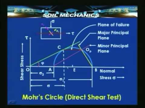
Let us take the example of some determination of important stresses using the Mohrís circle
in a direct shear test. We have the normal stress; we have the shear stress the 2 axis
typical of a Mohrís circle. Then suppose we have the sigma and tow values at failure.
Then sigma tow values at failure will belong to a point C typically as shown here. So this
point C has coordinates sigma and tow and that should corresponds to the normal stress
and shear stress on this failure plane because thats the point at which the Mohr envelop
touches the circle. And therefore this point C corresponds to failure and therefore the
Mohr envelop should pass through that and that should be tangential to the Mohr circle.
So now we can draw a Mohrís circle which will be tangential to this envelop at this
point. Now this being a drained test, direct shear test or usually drained test, cohesion
is not mobilized and therefore this intercept on the y axis C due to cohesion is zero. Now
if this is the envelop and if this is the Mohrís circle, obviously the major principle
stress will be OB and minor principle stress will be OA. It is of interest to know what
are their orientations. Magnitudes are available now from the Mohrís circle plot. Now what
are their orientations? For example if you take sigma1 to get its orientation we will
use the so called pole method which we saw in detail in the last lecture. Take this point
C, thatís the point whose stresses corresponds to that or rather those on the failure plane.
Therefore this point C is a point on a plane which should be parallel to this failure plane
and must intersect the Mohrís circle at the pole. So point C if you take and draw a line
parallel to the failure plane at C then it intersect the Mohrís circle at a point Op
which now becomes the pole. The property of the pole is that from the pole if you draw
a line parallel to any plane where it intersect the Mohrís circle gives you the stresses
on those planes. So for example if I draw a line up from Op to point B, since the coordinates
of B have major principle stress and zero as the values. Op must be therefore represent
the major principle plane thatís this yellow line because it passes through a point B whose
stresses correspond to the stresses on the major principle plane that is sigma one zero.
So the major principle plane is very easily obtained once you know Op while connecting
it to point B. Identically by the same method you can get OpA which will be minor principle
plane. So we know the orientation of the major and the minor principle plane if I transfer
them to this index sketch which I have here then this yellow line represents the direction
of the minor principle plane, this pink line represents the orientation of the major principle
plane. And this means that although before failure the major principle plane is horizontal
and the minor principle plane is vertical. At the time of failure the horizontal plane
become failure plane and therefore automatically the major and the minor principle planes take
up new orientations as given by these 2 lines and this an
…